Small displays are awesome for displaying data for any Embedded System. It is always fun to play around these displays.
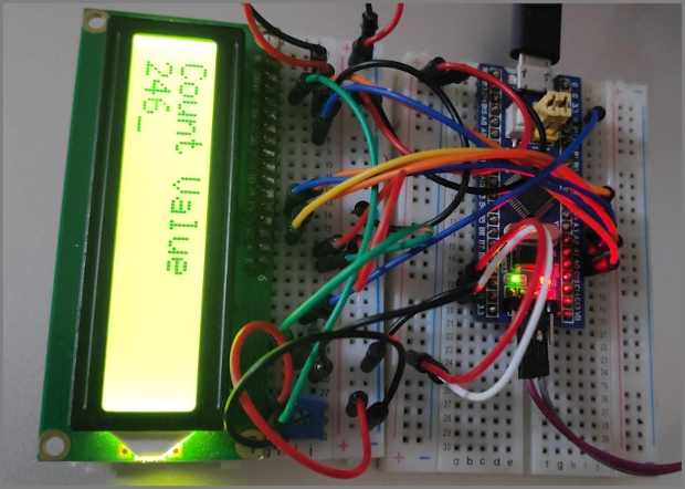
Table of Contents
About this Article
-
In this article we will be exploring one of such LCD display that is alphanumeric LCD 16x2, its Pin map, commands/instruction sets.
-
Will be interfacing it with STM32 and writing driver for its working.
Getting Started with LCD 16x2
Alphanumeric LCD are available in different sizes in terms of rows and columns, for example 16x1, 16x2, 20x4 etc. All these LCD display works with same principle except they can show less or more content.
LCD 16x2 is one of the most popular display in Embedded system.
Where 16 x 2 means
16 columns or 16 character
2 rows or 2 lines
Thus LCD 16 x 2 can show 16 characters in each of the 2 rows (lines).
LCD 16x2 Pin Map
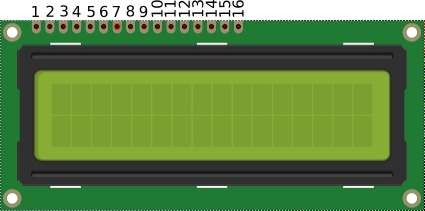
Pin Description
| Pin Number | Symbol | Pin Function |
|---|---|---|
| 1 | VSS | Ground |
| 2 | VCC | +5v |
| 3 | VEE | Contrast adjustment (VO) |
| 4 | RS | Register Select. 0:Command, 1: Data |
| 5 | R/W | Read/Write, R/W=0: Write & R/W=1: Read |
| 6 | EN | Enable. Falling edge triggered |
| 7 | D0 | Data Bit 0 (Not used in 4-bit operation) |
| 8 | D1 | Data Bit 1 (Not used in 4-bit operation) |
| 9 | D2 | Data Bit 2 (Not used in 4-bit operation) |
| 10 | D3 | Data Bit 3 (Not used in 4-bit operation) |
| 11 | D4 | Data Bit 4 |
| 12 | D5 | Data Bit 5 |
| 13 | D6 | Data Bit 6 |
| 14 | D7 | Data Bit 7/Busy Flag |
| 15 | A/LED+ | Back-light Anode(+) |
| 16 | K/LED- | Back-Light Cathode(-) |
Please Note: In this example we are only interested in Displaying Data (Data Write), thus R/W pin is connected to ground permanently (ie For data Write R/W should be Low).
LCD 16x2 Interfacing with Bluepill
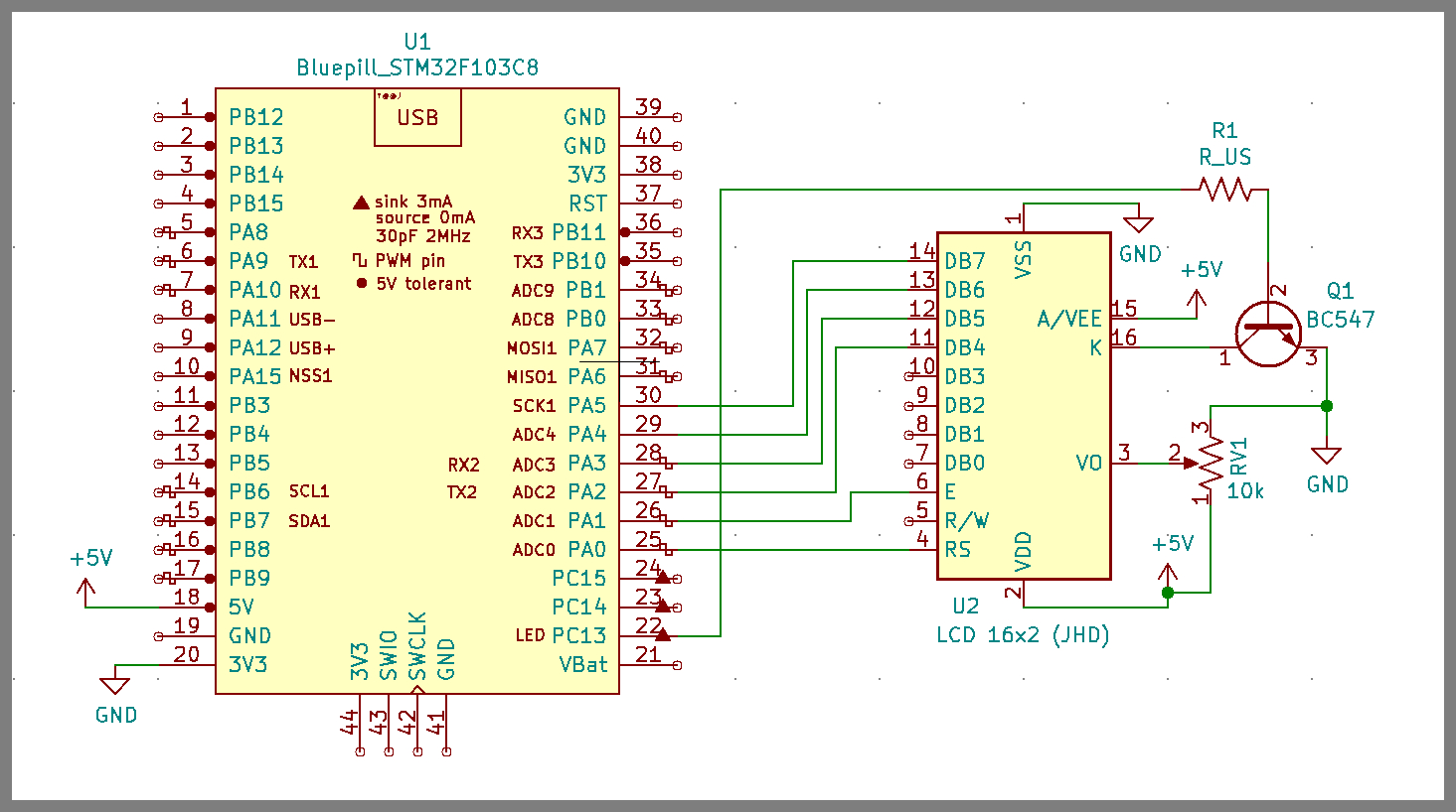
Control Pins
-
RS (Register Select Pin) is connected to PA0.
-
RW (Read Write Pin) is connected to GND as this article is only intrested to Write (Display) data on LCD 16x2.
-
En (Enable Pin) is connected to PA1.
Data Pins
-
D4,D5,D6,D7 LCD Data pins are connected to PA2, PA3, PA4, PA5 respectively.
-
Other Data pins (D0, D1, D2, D3) are left unconnected.
Please Note in this example we are operating LCD 16x2 in 4-Bit Data Lenght Mode.
Power, Contrast and Backlit Pins
-
Vss is Connected to GND and VDD is connected to 5v Pin.
-
Vo is connected to potentiometer of 10K to control the contrast.
-
Backlit Anode pin is connected to 5v and Cathode is connected to collector BC547 (NPN) transitor, Emiiter of transistor is grounded and the base of transistor is connected to PC13 to switch ON and OFF the backlit.
LCD 16x2 Commands/Instructions
Below is the image of some of the commands given in datasheet.
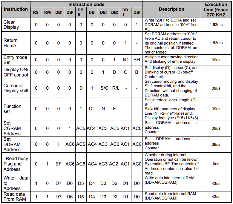
Lets Simplify these Commands
// Define Data Length, Number of Display Lines and Display font type (5x11/5x7)
-
For 8-Bit Mode (Data Length), 2-Display lines & 5 x 8 Display font type
- Command: 0 x 38
-
For 4-Bit Mode (Data Length), 2-Display lines & 5 x 7 Display font type
- Command: 0 x 28
// Define Display (ON/OFF), Cursor (ON/OFF) and Cursor Blink (ON/OFF)
-
For Display ON, Cursor ON & Cursor Blink ON
- Command: 0 x 0F
-
For Display ON, Cursor OFF & Cursor Blink OFF
- Command: 0 x 0C
// Define Entry Mode
-
For Increment Cusor and No Shift
- Command: 0 x 06 Acknowledgements and Resources
// Cursor Positions
-
For Cursor position to begining of First row/line
- Command: 0 x 80
-
For Cursor position to begining of Second row/line
- Command: 0 x C0
// Clearing Screen
-
For Clearing Screen
- Command: 0x01
LCD 16x2 Commands Sequences
Initializing LCD - 4-Bit Mode
To initialize LCD, send the following commands to it
0x28: for 4-bit data Length, 2-lines & 5x7 font type initialization.
0x0C for LCD display On, Cursor Off & Cursor Blink Off.
0x06 for Increment Cursor & No Shift.
0X01 for clearing the display of the LCD.
0x80 for positioning the cursor at first line .
Sending Command in 4-Bit Mode
Place higer nibble on data lines.
Write Low to RS Pin of LCD. (RS = 0)
Send High to Low pulse on EN Pin of LCD. (EN = 1; delay_ms(1); EN = 0)
Place lower nibble on data lines.
Send High to Low pulse on EN Pin of LCD. (EN = 1; delay_ms(1); EN = 0)
Sending Data in 4-Bit Mode
Place higer nibble on data lines.
Write High to RS Pin of LCD. (RS = 1)
Send High to Low pulse on EN Pin of LCD. (EN = 1; delay_ms(1); EN = 0)
Place lower nibble on data lines.
Send High to Low pulse on EN Pin of LCD. (EN = 1; delay_ms(1); EN = 0)
Lets Get into Writing LCD Driver
- The example main code, LCD driver and the complete STMCUBEIDE workspace for LCD 16x2 example can be found at LCD16x2_f103.
Starting with STM32f103xx_lcd_driver.h
STM32f103xx_lcd_driver.h is the header file for alphanumeric LCD driver and it will consist of followings:
-
Macros defining LCD type.
-
Macros defining the LCD Control and Data pin interfacing with STM32f103C8.
-
Member Functions/APIs for writing Data/Command, Setting Cursor, Shift left and right etc.
So lets start writing this header file.
1
2
3
4
5
6
7
8
9
10
11
12
13
14
15
16
17
18
19
20
21
22
23
24
25
26
27
28
29
30
31
32
33
34
35
36
37
38
39
40
41
42
43
44
45
46
#ifndef STM32F103XX_LCD_DRIVER_H_
#define STM32F103XX_LCD_DRIVER_H_


#include "STM32f103xx.h"				// including target header file

#include "STM32f103xx_gpio_driver.h"		// including GPIO Driver header file

/******************************************************************************************************
 * 	User can edit these macros for defining display type, LCD Control bits, LCD Data bits etc
*****************************************************************************************************/

 /****** Define Display Type here *********************************/

//Number of Rows of the display (upto 4 only)
#define LCD_ROWS			2

//Number of Cols of the display (16 or 20)
#define LCD_COLS			16

// Define Data Mode (4-Bit or 8-Bit) for Display operation

#define LCD_DATA_MODE		4	// or 8

//----------------------------------------------------------------

// Define LCD Control Port/lines (All Control lines should be on same Port)

#define LCD_CONTROL_PORT	GPIOA

#define LCD_RS_PIN			GPIO_PIN_NO_0
#define LCD_EN_PIN			GPIO_PIN_NO_1

//----------------------------------------------------------------

// Define LCD Data Port/lines (All Data lines should be on same Port)

#define LCD_DATA_PORT		GPIOA


#define LCD_D4_PIN			GPIO_PIN_NO_2
#define LCD_D5_PIN			GPIO_PIN_NO_3
#define LCD_D6_PIN			GPIO_PIN_NO_4
#define LCD_D7_PIN			GPIO_PIN_NO_5

//-----------------------------------------------------------------
License
- Distributed under the CC BY-SA 4.0 license.
